
Why PPF Patterns Don’t Fit: What to Check Before Recutting

A PPF pattern has been cut, the vehicle is ready, and installation begins. Then something looks wrong: a sensor opening appears off-center, one corner seems short, or the edge does not extend far enough for the planned wrap.
The immediate response is often to adjust the file and cut another piece. However, recutting without identifying the cause can reproduce the same problem.
PPF pattern fitment depends on the relationship between the vehicle, the selected file, the cutting output, and the installation process. A mismatch at any of these stages needs a different response.
The following checks provide a practical troubleshooting sequence. They are diagnostic starting points rather than proof of a particular fault. Work through them before changing the pattern or committing another section of film.
1. Identify the Fitment Problem Before Changing the Pattern
Start by describing what does not fit. “The pattern is wrong” is too broad to guide an adjustment.
Check whether the issue affects the entire panel, one opening, a particular edge, or the relationship between two reference points. Also record when it becomes visible: before positioning, during alignment, or after part of the film has been secured.
| What you observe | What to check first |
|---|---|
| The whole piece appears too large or too small | Vehicle selection, previous scaling, output dimensions, and intended installation method |
| The outline broadly matches, but one opening does not | Panel configuration, local edits, and alignment |
| One end aligns while the other moves out of position | Positioning sequence, film tension, and cutting output |
| The panel is covered, but an edge cannot be wrapped | Intended coverage and available edge allowance |
| Deviation appears greater along a long piece | Feed behavior, loading, and dimensional accuracy |
Photograph the initial condition before making changes. Once a piece has been stretched, trimmed, or repeatedly repositioned, it becomes harder to reconstruct the original problem.
A useful description identifies a location and direction: “The upper opening sits toward the outside when these two reference points are aligned.” That is more actionable than “the bumper does not fit.”
2. Confirm the Exact Vehicle and Panel Configuration
A familiar model name does not establish that every exterior panel matches the selected file.
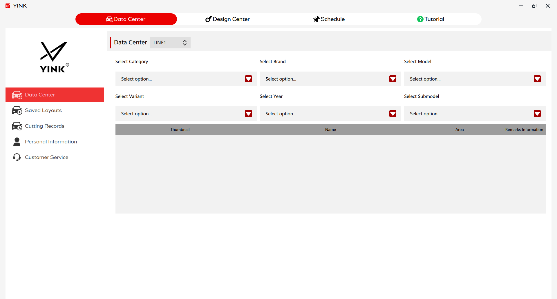
Check the model year, body style, trim, and market specification against the vehicle in the bay. Pay particular attention to facelift changes, appearance packages, bumper shapes, vents, sensors, and trim openings.
Registration year may not provide enough detail on its own. When identification is uncertain, use the vehicle information and visible panel features together. YINK’s guide to choosing the correct model year in YINK explains why the registration date may differ from the year grouping used for a vehicle generation.
Compare the Actual Features
Before recutting, compare the preview with several identifiable features on the vehicle. Look beyond the outer silhouette. The relationship between openings, corners, recesses, and trim boundaries can reveal a configuration mismatch.
Ask whether the vehicle has aftermarket parts or replacement panels from a different specification. A file selected for the original configuration may require further assessment when the installed component is different.
YINK’s guide to checks before editing in Design Center reinforces the importance of confirming the starting setup before modifying a layout. For fitment troubleshooting, vehicle and panel identification should come first.
3. Check the Pattern Version and Previous Edits
Once the vehicle is confirmed, establish which file was actually cut.
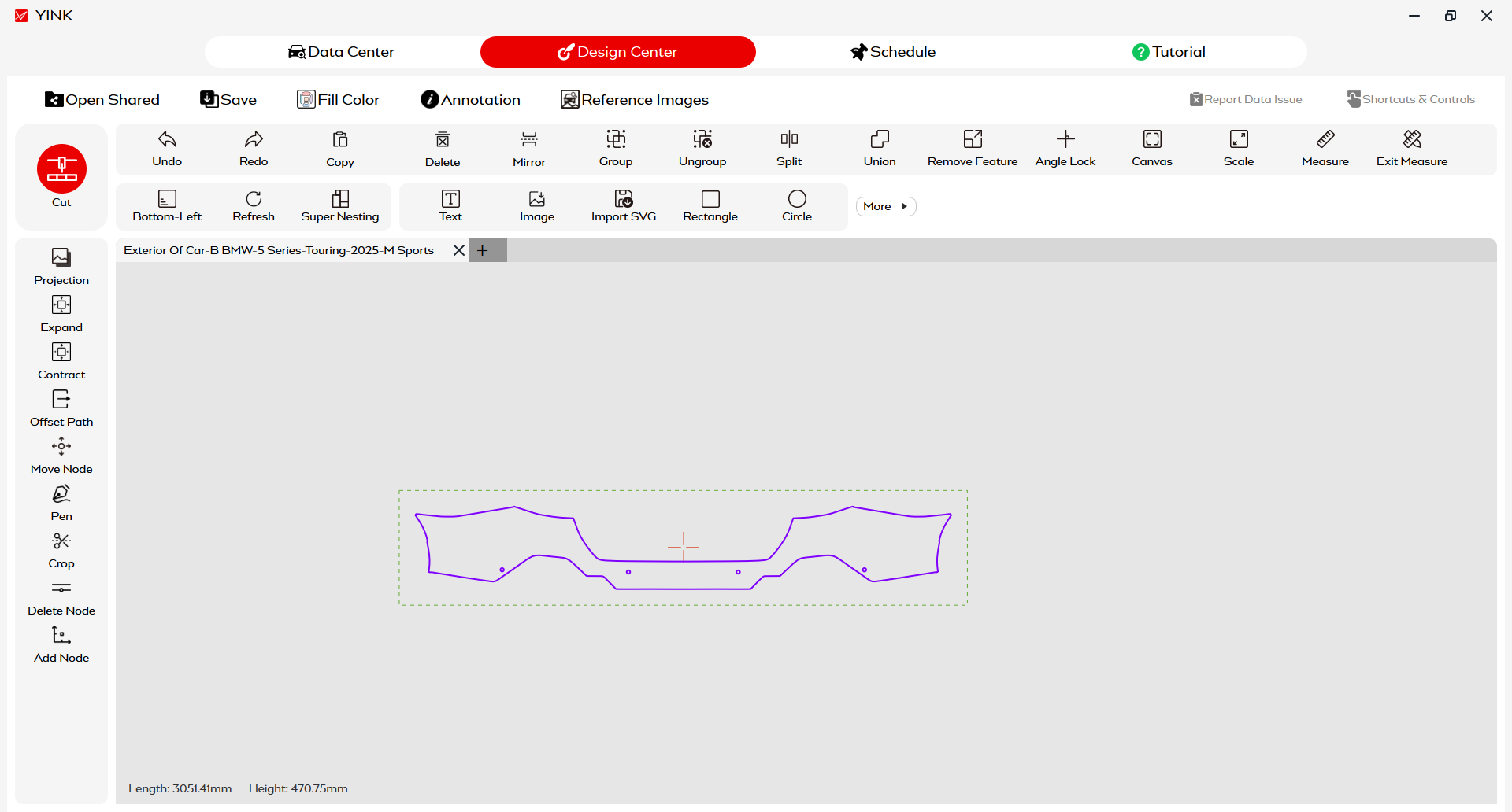
A saved layout may include changes made for another job: a modified opening, an extended edge, a local shape adjustment, or a scaling operation. Those changes may be appropriate for the earlier installation but unsuitable for the current one.
Compare the working file with an unchanged copy where available. Check the relevant dimensions and inspect the affected area rather than relying only on the filename.
Separate Coverage Choices from Shape Errors
A pattern designed to finish near a panel edge should not automatically be judged against a wrapped-edge installation plan.
Ask what the selected boundary is intended to achieve. Does it provide visible-surface coverage, additional material for an accessible return, or a different finishing approach?
Edge allowance and overall scale solve different problems. If one edge needs extra material, enlarging the entire piece can also move openings and alter otherwise correct boundaries.
YINK provides edge-expansion tutorials in its software operation guides. Use the relevant guidance to understand the tool, then assess the particular panel before deciding where an extension is appropriate.
Keep the original file available and label any revised version clearly. A useful label records the vehicle configuration, changed area, and intended coverage.
4. Verify Cutting Output Before Recutting a Full Panel
A correct file still needs to be reproduced at the intended dimensions.
Check the output settings, measurement units, selected machine configuration, and any scaling applied between the design workspace and the plotter. Distinguish layout space from actual geometry: changing the available canvas should not be treated as a method of correcting panel fitment.
Use a Measurable Test
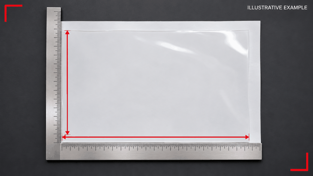
Before another full-panel cut, use a simple test shape with known dimensions, following the equipment manufacturer’s recommended procedure.
Measure the output in both directions while it remains flat and unstretched. Record the specified dimensions and the measured result. If they disagree, investigate the output process before altering vehicle geometry.
This test helps separate a dimensional output issue from a panel-specific concern. It does not, by itself, prove that a complex vehicle pattern is correct.
Inspect Loading and Feed Behavior
Check whether the material is loaded squarely, supported appropriately, and able to travel without obstruction. On equipment using pinch rollers, verify their placement according to the machine instructions. Observe whether the roll pulls unevenly or the material shifts during movement.
If deviation increases over a longer cut, investigate feed and dimensional accuracy rather than compensating immediately by editing the pattern.
Use instructions for the specific machine. The YINK Support Center provides model-specific installation and commissioning documents; these are a better starting point than applying settings from a different plotter.
5. Review Alignment and Film Handling During Installation
A flat cut piece and a curved vehicle panel do not provide a complete fitment comparison by simple visual overlay.
Evaluate the film using the positioning sequence and handling method appropriate to the panel and film product. Follow the film supplier’s instructions for application conditions, solutions, stretching, and adhesion. Manufacturer guidance can differ between products, so a universal stretch percentage or temperature would be inappropriate.
Compare More Than One Reference Point
One aligned opening does not establish that the whole piece is positioned correctly.
Check several relevant features before securing a large area. Observe how alignment changes as the film is positioned. If bringing one corner into place pulls an opening away from its intended location, stop and reassess the positioning and tension.
Avoid repeatedly stretching the film simply to make every boundary reach. That can obscure the original issue and make the next assessment less reliable.
Record When the Deviation Appears
Was the mismatch visible during initial positioning, or did it develop after one section was fixed?
If the same local deviation remains after vehicle selection, file history, output dimensions, and installation positioning have been checked, document it for further review.
The aim is to preserve evidence and narrow the cause. A workshop should be able to explain what was checked, what changed, and what remained consistent.
6. Decide Whether to Reposition, Edit, or Recut
The next action should follow the finding.
| Confirmed finding | Appropriate next step |
|---|---|
| Wrong vehicle or panel configuration | Select the matching file and reassess before cutting |
| Unintended changes in a saved file | Compare with the original and remove or revise those changes |
| Output dimensions do not match the test geometry | Resolve settings or machine issues and repeat the test |
| Positioning caused the deviation | Reposition only where the film condition and supplier guidance allow |
| The job requires a different edge finish | Assess a targeted boundary adjustment |
| A local discrepancy remains after the checks | Submit the file details and installation evidence for review |
A local mismatch does not automatically justify global scaling. Before changing a complete pattern, identify which dimensions or boundaries need correction and which already match.
Likewise, another cut is justified when it addresses a known cause: a corrected file selection, verified output settings, or an assessed modification. Cutting the same file again under unchanged conditions offers little diagnostic value.
After a successful correction, record the result. Keep vehicle-specific adjustments separate from the shop’s general working files so that an exception does not become an unexplained default.
7. What to Send When Requesting Pattern Support
A clear support request gives the reviewer enough context to reproduce the concern or compare it with the relevant data.
Prepare the following information:
- Vehicle details: make, model, model year, body style, trim, and market specification where known.
- Pattern identification: the selected panel, identifiable file information, and whether the file was modified.
- Overall photographs: the full panel and the film’s position relative to recognizable features.
- Close-up photographs: the affected location, with the direction of the mismatch clearly marked.
- Measurements: useful dimensions with visible reference points and units.
- Cutting information: machine model, film product, and the results of any dimensional test.
- Installation context: when the issue appeared and which positioning checks were completed.
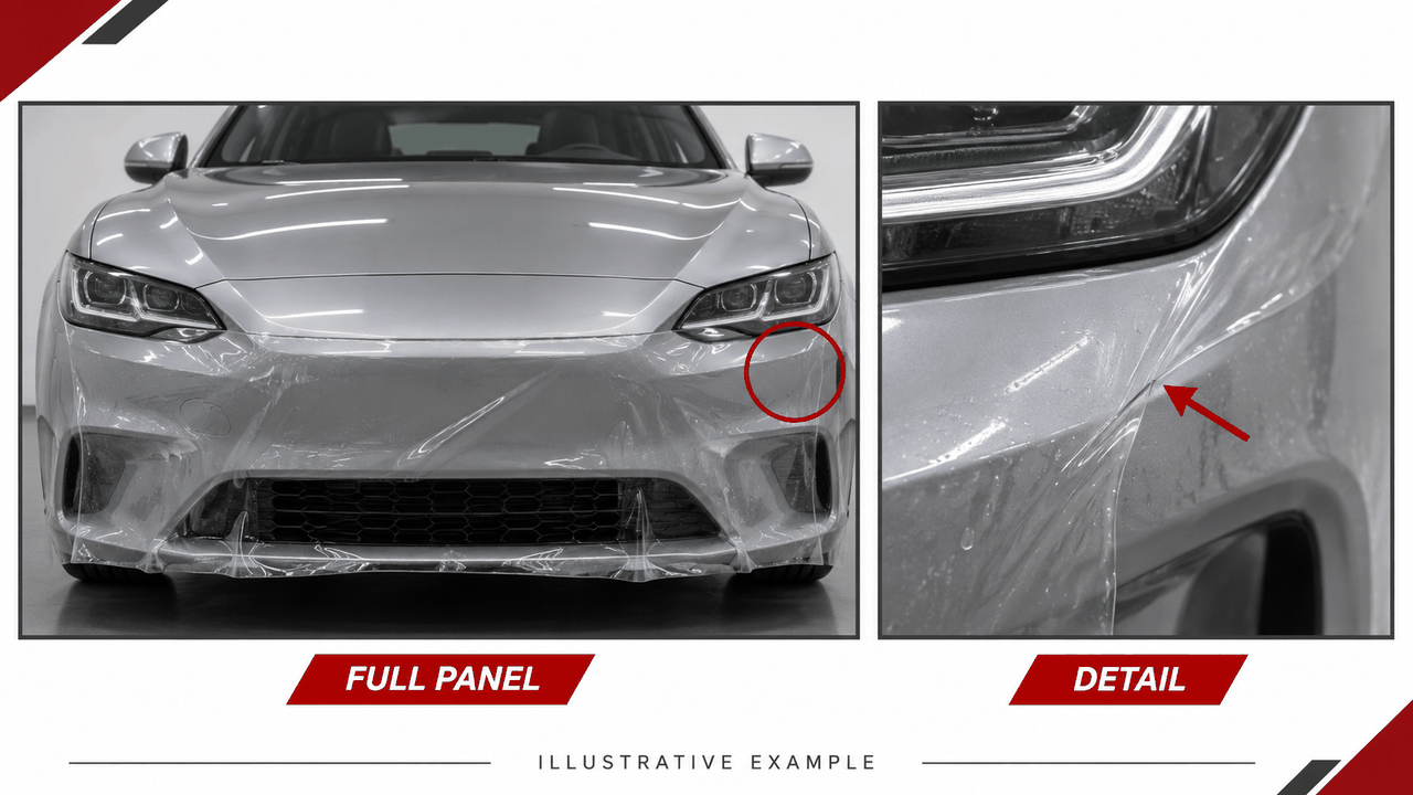
Photograph the camera-facing surface as squarely as practical, and include wider views alongside close-ups. A tightly cropped image can show a gap while hiding the surrounding alignment.
Contact YINK with this information when requesting assistance with a YINK pattern. The material provides a clearer basis for reviewing file selection, editing history, cutting output, and the reported discrepancy.
8. Frequently Asked Questions
Why is my pre-cut PPF pattern smaller than the panel?
Possible explanations include the intended edge clearance, a different panel specification, unintended scaling, or the installation method required by the pattern. Check the selected coverage and output dimensions before enlarging it.
Should I enlarge the entire pattern if one edge does not fit?
First establish whether the issue is local. Enlarging the complete piece changes other edges and opening positions. A targeted adjustment may be more appropriate once positioning, configuration, and output have been checked.
How can I tell whether the problem comes from the pattern or the plotter?
Begin with a known-dimension test shape. Incorrect test dimensions point toward the output process. Correct test dimensions narrow the investigation but do not confirm the vehicle file; continue checking selection, edits, and installation positioning.
Does pre-cut PPF always include wrapped edges?
No. Coverage depends on the particular pattern and selected finishing approach. Confirm the intended boundary and assess whether the panel provides suitable access for wrapping.
What photos help a support team assess a fitment issue?
Provide a full-panel view, clearly marked close-ups, and photographs showing several alignment references. Include vehicle and file details, measurements where useful, and an explanation of when the deviation appeared.
Before the Next Cut
When a PPF pattern does not fit as expected, move through the checks in order: vehicle configuration, file history, output dimensions, and installation positioning.
This creates a reason for the next action. Repositioning addresses alignment, a targeted edit addresses an assessed boundary requirement, and a new cut implements a verified correction.
If the cause remains unclear, share the evidence with YINK before proceeding. A well-documented problem is easier to assess than a series of unexplained recuts.
Post time: Nov-05-2026


