
How to Use 3D Imaging and Vector Engine in YINK Software(YINK FAQ Series — Episode 7)
How to Use 3D Imaging & Vector Engine in YINK Software?
Introduction
In real production environments, not every cutting job comes from a pre-made vehicle database. Many PPF, window tint, and vinyl shops often need to create custom patterns for special vehicle parts, logos, decals, or unique installation areas. This is where tools like 3D Imaging and Vector Engine become especially useful.
Within the YINK software workflow, 3D Imaging helps users generate cutting data from real object shapes and photos, while Vector Engine can convert images or graphics into editable vector cutting paths. Together, these tools help shops reduce manual drawing time, improve workflow flexibility, and handle more customized cutting applications efficiently.
For businesses that regularly work with custom projects, understanding how to use these two functions can significantly improve production speed and cutting accuracy.
Q1: How does 3D Imaging work and how to create accurate patterns?
What is 3D Imaging?
3D Imaging in YINK software is a feature that allows you to convert real vehicle parts into precise cutting data by capturing their actual shape.
It’s especially useful for:
- New models without data
- Special parts or custom areas
- Complex curved surfaces
How to use 3D Imaging?
Step 1: Create a physical template
Use masking tape to copy the shape of the target area 1:1.
Then trim and refine the shape carefully.


Step 2: Prepare background for measurement
Place the template onto a mosaic background board
(each square = 100mm × 100mm)
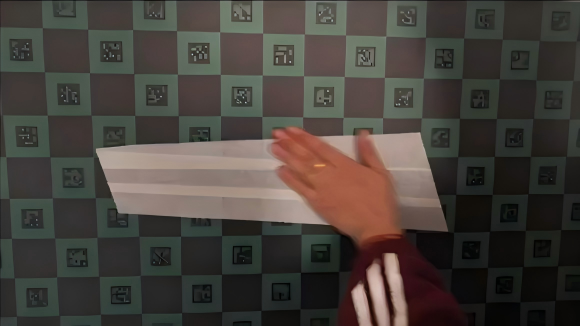
Step 3: Take a photo
Capture a straight, level photo of the template.
Step 4: Import into YINK software
- Save the image to your computer
- Open 3D Imaging in YINK
- Import the photo
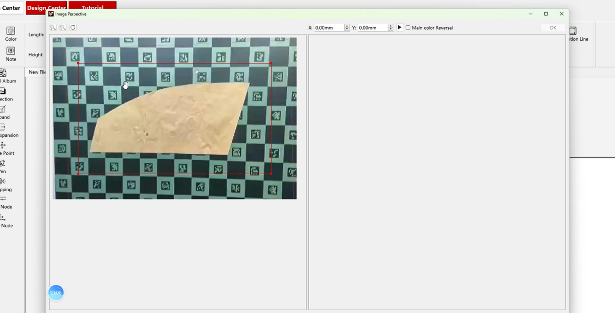
Step 5: Measure dimensions using grid
- Count grid squares:
- X-axis (horizontal)
- Y-axis (vertical)
- Example:
- 10 grids → X = 1000mm
- 5 grids → Y = 500mm
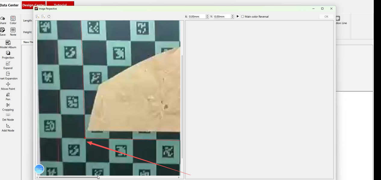
Step 6: Generate data
- Input X & Y values
- Click generate
- Background will be removed automatically
- Click OK to complete


Tips
- Ensure the photo is not tilted
- Always use full grid coverage for accuracy
- The more precise the template, the better the cutting result
Q2: How to convert images into cutting paths using Vector Engine?
What is Vector Engine?
Vector Engine converts bitmap images (like PNG) into vector cutting paths.
It’s ideal for:
- Logo cutting
- Custom graphics
- Branding elements on PPF
How to use Vector Engine?
Step 1: Prepare your image
Use a clear PNG or bitmap image.

Step 2: Open Vector Engine in YINK
Import the image file.
Step 3: Adjust settings
- Select Hyper Fine (highest precision)
- Turn OFF background removal
- Turn ON color inversion
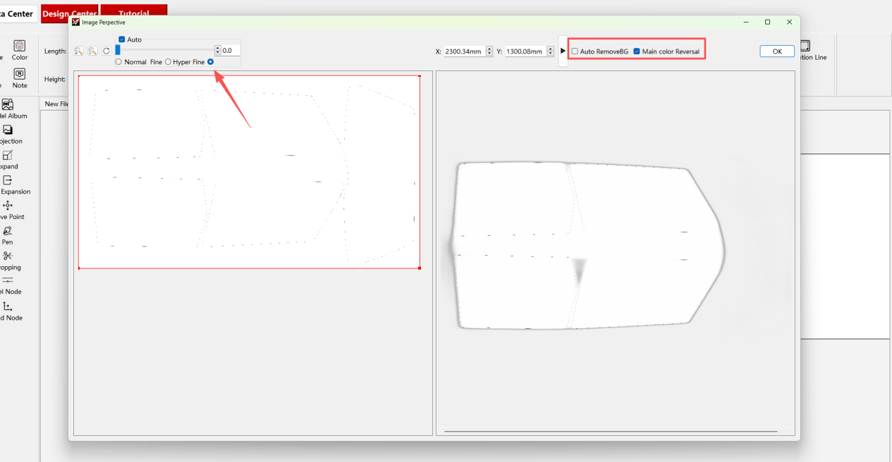
Step 4: Generate vector path
Click “Start” and wait for processing.

Step 5: Finalize
Click OK → vector data will appear and can be used for cutting.

When to Use 3D Imaging vs Vector Engine
| Feature | 3D Imaging | Vector Engine |
|---|---|---|
| Main Purpose | Create cutting data from real object shapes or photographed surfaces | Convert images, logos, or graphics into editable vector paths |
| Best Used For | Custom vehicle parts, irregular panels, special installation areas | Logos, decals, stickers, branding graphics, simple shapes |
| Input Source | Real photos with measurement references or grids | PNG, JPG, or graphic image files |
| Workflow Type | Shape reconstruction and contour generation | Image tracing and vector conversion |
| Accuracy Focus | Physical shape and surface contour accuracy | Clean line detection and graphic precision |
| Common Applications | PPF custom sections, architectural film edges, non-standard surfaces | Vinyl graphics, advertising materials, lettering, window decals |
| Skill Requirement | Requires careful photo alignment and scaling | Easier for general graphic editing workflows |
| Production Advantage | Reduces manual measuring and drawing time | Speeds up artwork-to-cutting workflow |
| Typical Problem Solved | No existing database template available | No editable vector file available |
| Recommended for | Installers handling custom fitting jobs | Designers and shops creating graphic-based cuts |
| Final Output | Real-world contour cutting paths | Editable vector cutting files |
| Workflow Flexibility | Better for unique or irregular shapes | Better for repeatable graphic production |
Common Mistakes to Avoid
When using 3D Imaging or Vector Engine, small setup mistakes can directly affect the final cutting result. Before sending the file to the plotter, users should carefully check the image quality, scale, and cutting path.
1. Taking Photos from the Wrong Angle
For 3D Imaging, the photo should be taken as straight and stable as possible. If the camera angle is tilted, the generated outline may become distorted, causing the final cut to be inaccurate.
2. Using Low-Quality Images
Blurry, dark, or low-resolution images make it harder for the software to recognize edges clearly. This is especially important when converting logos or graphics through Vector Engine.
3. Ignoring Scale Calibration
If the image size is not properly calibrated, the cutting path may look correct on screen but become too large or too small in actual production.
4. Not Checking the Vector Path
After the software generates the path, users should review the lines before cutting. Extra points, broken lines, or overlapping paths may affect cutting smoothness.
5. Sending the File to Cut Too Quickly
Do not send the file directly to the plotter without previewing it. A quick inspection can help avoid wasted material, wrong cuts, and unnecessary rework.
Conclusion
With both 3D Imaging and Vector Engine, YINK gives you the flexibility to:
- Create data when templates are unavailable
- Customize designs freely
- Expand your service beyond standard installations
These tools are especially valuable for shops looking to handle custom jobs and unique vehicles more efficiently.
Post time: Mar-26-2026


